
East Windsor Municipal Utilities Authority
7 Wiltshire Drive
East Windsor, NJ 08520
Phone: (609) 443-6000
Emergencies: (609) 448-5678
Waste Water Treament
East Windsor Municipal Utilities Authority Treatment System
Robert M. Boltner Advanced Water Reclamation Facilities
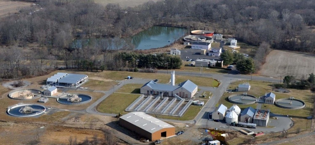
EWMUA’s wastewater treatment plant provides an invaluable public service for the residents of East Windsor Township. Wastewater is discharged from homes, institutions, and businesses, and is conveyed to the wastewater treatment plant (WWTP) by the sanitary collection system. The collection system comprises over 100 miles of sewer piping along with ten (10) pumping stations. Wastewater flows through the collection system primarily by gravity to the pumping stations where it is pumped to a point in the system where the wastewater may again flow by gravity. The wastewater then enters into the main trunk line that delivers it to the WWTP.
In 1989 to provide a higher level of treatment to meet the stringent water quality criteria of the Millstone River (receiving stream) and to increase plant capacity to 3.35 mgd construction began on the new upgraded and expanded wastewater treatment plant. In 1992 the new advanced wastewater treatment facility went on-line. Then, in 2010-2012 the wastewater treatment plant went through another upgrade to 4.45 mgd to continue to meet the changing water quality criteria in the Millstone River and to keep pace with the Township’s growth.
Today, the plant treats sewage to meet stringent state and federal standards before releasing it to the Millstone River.
HOW THE WASTEWATER IS TREATED
Preliminary Treatment
Preliminary treatment removes both large and small objects from the raw wastewater (influent) as it enters the treatment plant.
As the wastewater enters the WWTP, it passes through a screen where materials which would interfere with the treatment process are removed. These materials call “screenings” are a diverse assortment of paper, plastics, pieces of wood, trash, and rags.
The wastewater then enters the influent wet well, from which two (2) of the four (4) influent pumps lifts the flow allowing it to flow by gravity to the downstream treatment units. In addition, during periods of high flow the two remaining influent pumps are used to pump excess influent to two (2) equalization basins. During low flow periods (generally in the early morning hours) wastewater is returned to the influent wet well to be pumped to the downstream treatment units. This equalized flow maintains a more uniform treatment of the wastewater.
Continuing its flow, the wastewater passes through a flow meter, and then under Millstone Road to the main treatment processes where it enters two (2) cyclonic grit removal units. The grit material is mostly made up of non-biodegradable material such as sand and other fine solids. The grit is removed from the wastewater, washed and trucked off-site along with the screenings.
Primary Treatment
Primary treatment is a physical separation process which allows the heavier solids to settle to the bottom of the tank and floatables such as oil and grease float on the wastewater surface for removal. The primary treatment process consists of two (2) circular settling tanks and three (3) primary sludge pumps that pump the settled solids from the settling tanks to the solids handling facilities.
The wastewater flows on through to a distribution box where it is split and distributed to two (2) primary clarifiers (settling tanks). This process is where most of the suspended solids settle out of the wastewater, are collected and then removed by the primary sludge pumps. The floatables (scum) are removed from the surface of the wastewater and pumped to the sludge holding tanks. The primary clarifiers remove asubstantial portion of the heavier solids as well as some of the biochemical oxygen demand (BOD) pollutants. At this point the waterborne pollutants have been reducedconsiderably. More than15 percent of the BOD and 50 percent of the suspended solids have been removed. From the primary settling tanks the flow is delivered to the aeration basins for biological secondary treatment.
Secondary Treatment with Biological Nutrient Removal– Activated Sludge
Secondary treatment is the process where soluble and fine suspended dissolved materials remaining after primary treatment are removed. In addition, the EWMUA WWTP must also remove ammonia and phosphorus. Nitrogen and phosphorus are nutrients (such as those found in your typical lawn fertilizer) which if discharged in the WWTP’s effluent would result in a negative impact to the aquatic environment of the Millstone River. Since nitrogen and phosphorus are nutrients they can accelerate the growth of aquatic vegetation resulting in a decrease in the receiving water’s oxygen content. The decrease in oxygen content will decrease the water’s ability to support aquatic organisms.
As the wastewater leaves the primary clarifiers it enters the aeration basin distribution chamber where magnesium hydroxide is added for alkalinity control before being distributed to the two (2) aeration basins. The aeration basins – the heart of the biological treatment process – provide an environment for microorganisms to grow and consume the organic pollutants (BOD) found in the wastewater. Two (2) turbo blowers supply air to the aeration basins to provide both oxygen and sufficient mixing to bring the organic pollutants into contact with the biological mass of microorganisms (mixed liquor suspended solids-MLSS) within the basins. This enables the microorganisms to multiply very rapidly, cleaning the wastewater by feeding on the organic pollutants, thus reducing the BOD. The residence time for the biomass is sufficiently long to permit the growth of specialized microorganisms for the removal of nitrogen compounds (nitrification and denitrification).
The treated wastewater and MLSS flow from the aeration basins to the clariflocculators.
Secondary Clariflocculation and Phosphorus Removal
Secondary clarification is the process where the biomass and treated wastewater from the aeration basins are separated. The MLSS settles to the bottom of the tank for removal and the clarified treated wastewater flows from the tank. The secondary clarification process consists of three (3) circular clariflocculators, three
(3) return activated sludge (RAS) pumps and two (2) waste activated (WAS) sludge pumps which are housed in the secondary sludge pump station.
The treated wastewater and MLSS flows from the aeration basins to the secondary clariflocculator distribution chamber where alum is added for phosphorus removal. Phosphorus is removed chemically through the addition of aluminum sulfate (alum) to the MLSS prior to clarification. Phosphorus produces a precipitate that is removed with the solid in the clarification process.
The flow is then distributed to the three (3) Clariflocculators. The distribution chamber contains a mixer to provide contact between the alum and MLSS. The clariflocculators contain four (4) flocculators that gently mix the MLSS and alum before entering the clarification portion of the basin. The MLSS will settle to the bottom of the basin for removal. A portion of the solids removed in the secondary clarification process is returned (RAS) to the aeration basins to maintain the biomass population, while a significant portion of the settled solids are wasted (WAS) from the system to the Solids Handling Facilities. The clarified wastewater (effluent) flows from the clariflocculators to the sand filters.
When the wastewater leaves the clariflocculators, nearly 90 percent of the suspended solids and 95 percent of the BOD have been removed. In addition, ammonia- nitrogen and phosphorus have each been reduced to less than one milligram per liter.
Gravity Sand Filters- Final Effluent Polishing
Filtration is a physical process where wastewater is passed through a filter media (such as sand) to remove suspended solids.
Flow from the clariflocculators enters the filter distribution chamber where the it is distributed to the three (3) gravity sand filters. The sand filters consist of individual cells filled with approximately 10 inches of sand. The sand filters operate automatically when cleaning of the cells are required. The three (3) gravity sand filters polish the final effluent by removing any remaining suspended solids found in the clariflocculators’ effluent. This polishing process is designed to ensure a continued overall BOD and suspended solids removal of better than 95 percent. The final effluent leaves the filters and flows back under Millstone Rd. to the disinfection process.
Ultraviolet Disinfection
The disinfection process decreases the risks associated with waterborne disease causing organisms (pathogens) discharged from the WWTP into the receiving waters, protecting the water quality for subsequent downstream use.
Disinfection is accomplished through ultraviolet (UV) lighting submerged in the final effluent. There are two (2) channel with 2 banks of thirty (30) UV lamps each.
The final effluent flows into the UV distribution chamber where it is distributed to two(2) channels. The final effluent passes through the UV lamps in each channel before being discharged to the Millstone River.
Solids Handling and Disposal
Sludge is the name given to the solids that are separated from the wastewater in the treatment process. Processing and disposal of sludge is a major part of any wastewater treatment process. Raw sludge is generated by the settling process in the primary settling tanks, while biological solids are generated from the secondary settling process.
Gravity Thickeners
The primary purpose of thickening sludge is to reduce the volume of material that will be handled in subsequent processes. Gravity thickening is a physical process which concentrates (thickens) sludge through settling.
The gravity thickening process consists of two (2) circular tanks and two (2) thickened sludge pumps. Raw sludge is pumped to the gravity thickener distribution box from the primary settling tanks. The sludge is discharged to the gravity thickener where it settles to the tank floor and thickens. Periodically the thickened sludge pumps turn on and pump the thickened sludge to one (1) of the two (2) adjacent sludge holding tanks. The thickener overflow goes back to the head of the primaries for treatment.
Drum Thickener
The drum thickening process is a mechanical method for concentrating (thickening solids).
The drum thickening process consists of dual polymer systems, a flocculation tank, a drum thickener and a thickened sludge pump. The drum thickener is made up of a rotating screen which allows the water to be discharged from the sludge as it rotates from the front to the back end of the drum. Waste activated sludge is pumped from the secondary sludge pumping station via one of two (2) waste activated sludge pumps. The waste activated sludge is pumped to the drum thickener mixing with polymer, flocculated in the flocculation tank and then discharged into the drum thickener. When the thickened sludge reaches the end of the drum it is discharged into the sludge well below, the thickened sludge pump pumps the drum thickened sludge from the well to the sludge holding tanks where it is mixed with the gravity thickened sludge. The drum thickener can process up to 300 gpm of waste activated sludge.
The piping system also allows for the drum thickener to receive sludge from the gravity thickener.
Sludge Disposal
Sludge produced at the EWMUA’s wastewater treatment plant is disposed of off-site and incinerated.
Sludge from the sludge holding tanks is pumped via the thickened sludge transfer pump to a contract sludge hauler’s tank truck for transport off-site.
System Monitoring and Control –SCADA
All of the facilities associated with the EWMUA’s WWTP and collection system are monitored and controlled through a system wide supervisory control and date acquisition (SCADA) system. This system enables operational staff to monitor and control the plant processes remotely and from any location within the plant. It also enables the operational staff to monitor and control the operations of the ten (10) pumping stations within the collection system remotely and from the central monitoring station and collection’s office. The system also provides alarm notifications for both the plant and collection system pump stations.